|
Former Drake R8 Communications Receiver Email Mailing List FAQ |
IMPORTANT ANNOUNCEMENT
The information provided here was from a former Yahoo Drake List. Since this list is no longer running, I suggest trying the Drake R8 list at Draker8 on Groups IO!
Click on the above photo if you wish to download the full size image! (File Size: 320 Kilobyte).
This FAQ (or "Frequently Asked Questions") will hopefully answer any basic questions about this World Wide mailing list reflector. This FAQ was prepared by Stephen Newlyn VK5VKA with help from Mik Butler. (Moderator of the List)
Please read this information carefully!
|
M E N U |
Drake List Questions
How do I subscribe or unsubscribe to the list?
How do I send a message to the list?
What is permitted in messages?
Are off topic messages permitted?
Are subscribers to the list protected from SPAM (Junk Email)?
Drake Related Questions
Is there any computer software available for my Drake Receiver?
Are there any Drake related Web Sites?
Are there any books about the History of the Drake Company?
Were there any Drake receivers that had the Y2K bug?
Is it true that later versions of the R8B tune down to 10 Kilohertz?
How
do I find out when my Drake R8B was made?
Is it true that Drake no longer repairs any of their Shortwave (HF) Receivers?
Drake Modifications
The clocks on my Drake R8A are erratic. Can this be fixed?
Keypad buttons on my R8A don't work well. Any suggestions?
Can my Drake R8A/B Tuning knob be improved? It's too light!
The frequency hops/jumps on my R8B when using Main Tuning knob! Is there a fix for this?
DL7MAJ's R8 Tone Control, Back-up Battery, Power Consumption and Notch Modifications?
A Final Note
Please contribute to the List!
|
Drake List Questions |
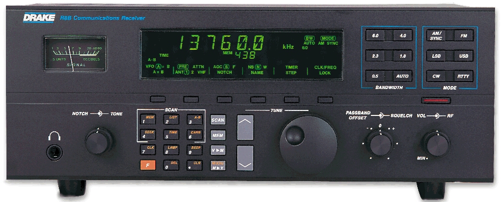
The list was for subscribers to discuss all aspects of the Drake R8 series (R8, R8A, R8B and R8E (European Model of the R8A)) of communication receivers as well as the Drake SW1, SW2 and SW8 series of Drake receivers. All of these receivers are no longer manufactured. The last brand new R8B was sold in 2005. To find a used receiver try Ebay, other on-line auction sites, radio receiver dealers or look in printed magazines or Radio User Magazine (UK).
The list also provides for various tips and hints on how to get the best out of your Drake receiver and also discuss any problems that may occur. Announcements of Drake-related products (software, add-ons etc) are also permitted.
How do I subscribe or unsubscribe to the list?
As this is a manually operated list there is only one address for both subscribing and unsubscribing.
To SUBSCRIBE: Send an Email message to < > requesting in the body of the message to be on the list.
To UNSUBSCRIBE: Send an Email message to < > requesting in the body of the message to be deleted.
This address is also used for address corrections and comments directed to the moderator (Mik Butler). Remember; additions and deletions are done manually so expect some delay in processing. There is no need to place SUBSCRIBE or UNSUBSCRIBE in the subject field. (But you can if you wish)
How do I send a message to the list?
Send your message to <>, remember your message will be read by all who subscribe to the list. Don't be surprised that sometimes you will not see many messages. The list operates only when people have something to say.
What is permitted in messages?
The list exists due to the generosity of Hewlett-Packard (HP) agreeing to provide one of its employees (Mik Butler) the disk space and Internet access to run this list as a purely personal activity. HP has no involvement in the list or its contents. With that in mind, the following is NOT permitted:
Obscene language, Sarcasm or Written Abuse.
Mild joking is OK, with emoticons permitted (-:.
Are Off Topic Messages permitted?
It depends how off topic they are. If postings do go off-topic then a private e-mail is sent to the originator of the offending message reminding them of the purpose of the list.
Not actively. It's implemented as a mail reflector. People whose postings contain obscene language, abuse, or who continually post off-topic messages will be chopped, but that's the only moderation performed.
Are subscribers to the list protected from SPAM (Junk Email)?
Any domains which produce spam or don't take effective steps to prevent spam originating from their domain are prohibited from posting to the list. List members who have an e-mail address at one of those domains are informed why their posts will be silently ignored, although they will still receive postings from the list.
|
Drake Related Questions |
Is there any computer software available for my Drake Receiver?
Note: Only the Drake R8, R8A, R8B and R8E (European Model of the R8A) had computer support!
For IBM Compatibles there are a number of packages available. Some include Ergo, RxPlus and Scancat. These packages offer different features for different applications. It is advisable to check out their Web Sites for further information to see which software package suits your particular needs. Most sites offer Trial or Shareware versions to download. Also available is R8PC software. It's only available for the "DOS" operating system and is available free of charge at the Drake Virtual Museum. Please read the instructions for this software to see if it is suitable for your receiver and/or your computer.
For Macintosh look for "Shortwave Navigator".
Are there any Drake related Web Sites?
Apart from R. L. Drake company web site there are few. One of the most extensive is the Drake Virtual Museum This site shows almost all the equipment Drake has manufactured. This site also has links to other Drake related sites. Definitely worth the visit.
Are there any books about the History of the Drake Company?
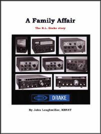
Yes, a book released in early 2001 gives a good insight into the company plus it has technical tips for some of Drakes earlier equipment. However the book does not cover the SW1, SW2, SW8, R8, R8A, R8E or the R8B in any great detail.
BOOK REVIEW by Stephen Newlyn VK5VKA
This 290 page publication gives a behind the scenes view of the R. L. Drake Company history from its beginnings in the year 1943 to the late 1990's (with the emphasis on Amateur Radio Equipment manufactured between 1943 and the early 1980's). It traces the company from when it developed bandpass filters such as the "F15/U" for the US military during World War Two, up to and including the TR-5 Amateur Radio transceiver.
A Family Affair
The author John Loughmiller deals in the first 100 pages with the history of the company and presents a look at most of the significant Amateur Radio products manufactured by Drake. The book also looks at how the "personalities" of various personnel shaped the company and how this in turn developed unique and reliable products that Drake is world known for. Rare black and white photos of Drake equipment are also featured as well as photos of the Drake factory and some of its employees.
This section also examines Drakes successes and also some of its failures. You'll also learn little snippets of information like as to why the former Drake plant at 540 Richard Street had no "Drake" name on it.
Technical Tips
The remaining pages are full of technical tips from Drake owners and collectors. Featured also are photos of Drake users and their radio shacks. An interesting section is the complete January 1977 Drake Radio Communications catalogue and also a section on how to correctly grade used radio equipment with terms such as Mint, Excellent, Very Good Condition, Good Condition, Fair, Poor, Bad and Restored.
Summary
This book is a must have for Drake aficionados, however in some
chapters like 10 and 11; you would need an understanding of
Electronics to understand the points of the chapter. Also
missing was a discussion on the Drake SSR-1 receiver (although
there is a picture in the book). This receiver although made in
Japan was designed by Drake and it would be interesting to get
an insight into the design of this receiver; as for many
SWLs/DXers, this was one of their first Drake receivers. All in
All an excellent publication. To obtain a copy; check your
favourite radio bookshop or try Universal or Grove Enterprises for more information.
Were there any Drake receivers that
had the Y2K bug?
As far as we know, there were no potential problems.
Is it true that later versions of the R8B tune down to 10 Kilohertz?
Yes the newer R8B's came with a revised ROM chip that allows the CPU to tune down to 10 Khz, the front-end of the receiver doesn't have a dedicated bandpass filter (BPF) for the VLF range. There is considerable attenuation below 100 Khz because of this and therefore performance is down to what it could be.
What is the life expectancy of the backlighting for the LCD in the SW8? What technology is employed? Incandescent? LED? Are spares available?
The backlight on the SW8 uses a single bright yellow LED with a fiber optic "light pipe" system that feeds the light to a diffusing panel behind the LCD. Since LED's can last for decades, the life expectancy should be very long, probably the useful life of the receiver. Drake says they have never had to replace one. This method of backlighting does offer the possibility of changing the colour if you don't care for yellow. The 'R8' series uses an array of "56" LED's behind the LCD! I guess they used this approach because a single bright LED wasn't available when the "R8" series was first designed. Fibre optics were also quite new then. It apparently wasn't economical to change later models of the "R8" series backlight to the type used in the SW8.
How do I find out when my Drake R8B was made?
The first digit in the serial number represents the year, 9 = 1999, 0 = 2000, 1 = 2001, etc. The second digit is a letter and
represents the month, A = January, B =
February, C = March, etc. The next four letters represent
the model number. The last four digits are the unique serial
number to that particular unit.
Is it true
that Drake no longer repairs any of their Shortwave (HF)
Receivers??
Yes! According
to an e-mail from a former Drake employee dated 2012, Drake
been sold to another company who have zero interest in
Drake's history of Communication Receivers. As a result, all
repairs have ceased on all models up to and including the
R8, R8A, R8B and R8E.
|
Drake Modifications |
ATTEMPT THESE MODIFICATIONS AT YOUR OWN RISK!
The following article was written by J. W. Schermerhorn.
Here's a description of the R8B "backlight
mod" that I did using four bright white LED's. Note: 'R' =
Remove
1. R- Front panel knobs. (set screws) The original R8 uses a
set screw on the metal tuning knob. The A&B model tuning
knobs are plastic and pull off. It can be hard to do if it's
never been off before.
2. R- Front panel (black) with clear display window. (screws
on top & bottom of panel)
3. R- Metal panel that holds two keypad membranes in place on
their contact boards. (several screws) Set the keypads aside.
4. R- Front chassis frame from main frame. (two screws on each
end) Pull the front chassis forward from the main frame for
better access. Don't stretch the connecting wires too much.
5. R- Multi-wire (blue) connector from the back side of the
LED PCB. (PCB means Printed Circuit Board)
6. R- LCD display mounting screws on front chassis. (four
screws, two on each end of the LCD) This is why you had to
remove the metal frame that covers the keypad membranes. The
two LCD screws on the right are not accessible with the keypad
frame in place. If you want to make it easier to remove these
LCD screws again, cut two semi-circular notches in the keypad
frame where it covers the two LCD screw heads. I did it with
my "Dremel" tool using a metal milling bit. You won't have to
remove the keypad frame again to access the right pair of LCD
mounting screws.
Carefully remove the LCD with the LED backlight PCB still
attached, from the front chassis frame. There may be a screw
near the S-meter to remove.
7. R- Six screws that hold the LED-PCB to the off/white
plastic LCD frame. Keep your fingers clean so you don't
contaminate the contacts on the LCD side of the LED-PCB.
You now have the LCD assembly with it's rear plastic frame
ready to install the white LED's. I used part # 900-7863 from
the "Radio Shack.com" catalog. These are bright white 3-mm
dia./ 4.0-V/ 20-ma/LED's. You need four of them at $US3.49-ea.
I installed two white LED's in each end of the LCD plastic
frame. Space each pair about 1.5-cm apart and a few "mm" above
the rear surface of the LCD. Drill the appropriate size holes
for a snug fit so they won't move around in the frame. The LCD
plastic frame material is quite soft. Don't push the LED's too
far into their holes. If they protrude on the inner surface of
the
frame, it might make the light uneven behind the LCD. I had to
reposition two of them to eliminate a "spotlight" effect. Make
sure you don't lose the piece of white cloth material behind
the LCD. It's there to diffuse the backlighting.
Now you have to decide on how to power the white LED's. I used
the 5.0-V DC supply line on the LED board that can be tapped
at pin #12 of the blue connector that you removed from the
rear of the LED-PCB. If you use a 5.0-V source with the white
LED's that I used, it will require a current limiting resistor
of about 150 ohms in series with one lead of each LED. The
remaining leads must go to a ground point on the PCB. The
disadvantage of using pin-12 on the LED PCB is that it's
always powered, even when the receiver is off, so the
backlight is always on. I got around this by installing a
small 12.0-V relay to control the 5.0-V line. The relay is
powered by the 11-16V -switched- source from the power supply.
Since this voltage source is turned off by another factory
installed relay on the power supply PCB, the 5.0-V line to the
white LED's will be turned off by the relay I added. There are
other possibilities for powering the white LED's, including
using the 11-16V source mentioned above. There is also a
10.0-V switched source available at the power supply. Either
of these sources will require larger value current limiting
resistors to keep the voltage/current within specs for the
LED's. Ohms law at work!
Using white LED's will produce a display with white characters
on a blue-green background. The blue-green color is apparently
intrinsic to the physical structure of the LCD material. It
may also pick up a little green from the PCB behind it. I find
the new backlight more pleasing than the "drab" OEM green. I
think the characters have better definition too. You could
experiment with putting a colour filter in front of the LCD or
try bright blue, red or orange LED's too.
Of course you have to turn off the original green LED's on the backlight PCB. I simply clipped them off the board with a snipper tool. If that sounds too "final" for you, you'll have to get into the schematic to figure out how to remove the power from the green display LED's (56 of them) without losing the six behind the S-meter. I decided it wasn't worth the effort. I also think the white backlighting works better if the green ones are removed.
Their presence might add some green to the white light. I left the six behind the S-meter. Actually, I had already changed those six to regular yellow LED's a while ago.
Be careful when reinstalling the backlight PCB to the rear of the LCD frame that you keep the (many) LCD control contacts clean. This is important so all the character segments of the LCD will work properly. I cleaned the contacts on the PCB with some alcohol just to be sure. You should also be careful not to contaminate the two "Zebra" strips that are embedded in the rear edges of the LCD frame where it makes contact with the LED-PCB. The strips look like a sandwiched layer of black between two pink layers. The material is spongy. These strips transfer the control signals between the PCB contacts and the rear of the LCD. After reading the above, I can imagine that some of you may be thinking I have too much time on my hands! I've always enjoyed "improving" my receivers over the years. It started with a Hallicrafters S20-R. When I got done with it, the circuitry was unrecognizable from the original design but the performance was greatly improved. I bought another S20-R for parts so I could restore the first to OEM condition. I guess it raises the question of how much you can change a receiver and still have the original item.
The clocks on my Drake R8A are erratic. Can this be fixed?
This depends on a number of factors, however, before sending it off to get repaired, try the following. Power off the receiver from any power source for at least 2 days. This allows for any residual voltages and/or corrupt memory to dissipate from the clock circuit. After the boot-up process, re-set the clocks. The clocks should now be back to their ever accurate self.
Keypad buttons on my R8A don't work well. Any suggestions?
To change or clean the keypad button assemblies, you have to remove all the front knobs and then the outer front (black) panel. This will expose the inner front panel frame. Each area of buttons is a rubber membrane which is held in place by a metal frame with screws around it. Remove each frame and take out the key membranes. Wash them carefully with a "soft" brush (no abrasives) in distilled water with a little liquid detergent. Be sure to clean/brush the electrical contact area on the backside of each key button. Rinse the membranes in distilled water several times and let them air dry.
While you have the key membranes removed, you should clean the gold colored contact traces on the printed circuit boards where each key touches them. Use some 91% isopropyl alcohol on a "Q" tip swab. Don't rub the contact traces too hard.
This is a project you can do if you're confident about working on electronic equipment, otherwise let Drake do it. The Drake part number for the 31-button key membrane kit is 2055191
Can my Drake R8A/B Tuning knob be improved? It's too light!
The knob can be removed by pulling it towards you firmly. Some ways of making it heavier include the following.
Fill the hollow back of the R8A/B knob with a mixture of epoxy (slow curing) and steel ball bearing's. It creates a smoother feel because of the increased mass/momentum. This doesn't put any significant stress on the rotary encoder because it's supported at the rear (behind the encoder wheel) in addition to the shaft in front. I haven't noticed any wear/looseness since I weighted the knob several years ago.
Another suggestion includes using the tuning knob from an Icom IC-R72 which apparently fits very well and is ideally weighted.
The frequency hops/jumps on my R8B when using Main Tuning knob! Is there a fix for this?
The problem is very likely the tuning encoder wheel which is on the opposite end of the tuning knob shaft inside the front panel. The only reliable way to fix this is to replace the encoder. It is possible to clean it with some electronic spray like "DeOxIt" but it's very difficult to get the spray inside the encoder without taking it apart and (you guessed it) it's not made to be disassembled.
It's also possible that the contact "fingers" of the encoder wheel assembly have become misaligned. In that case cleaning won't correct the problem. You can order just the encoder wheel assembly without it's PC board, which is not really needed. The part # is 3260012. It costs about $US12.00. Contact the Drake service department for it. Installing the new encoder assembly is not too difficult if you know how to solder well and are not timid about removing the covers and front panel of the radio.
It begins with removing all of the front panel knobs. The small ones have set screws. The big tuning knob pulls off. Remove the top and bottom covers of the radio along with the front (black) panel. This exposes the inner front chassis panel. Unscrew the hex nut that holds the tuning shaft/encoder assembly to the front chassis. This will allow you to remove the encoder with it's PC board from the rear of the front chassis. You must also unplug the three wire connector that runs from the encoder PC board to one of the radio's main PC boards.
Now you're ready to prepare the new encoder for installation. Since you're not going to use the old encoder PC board, you must unsolder the three wires from that board and resolder them to the three matching terminals of the new encoder assembly which doesn't have a PC board. Put the new encoder shaft through the front chassis hole where the old one was and secure it with the hex nut. Plug the encoder wiring connector back on the main PC board. Reinstall the front (black) panel, top and bottom covers and all the knobs.
Drake R8
Modifications by DL7MAJ
1) Improve the tone control for a better bass response.
2) Backup Battery for the internal clock.
3) Reduce power consumption when the R8 is switched off.
4) Notch Circuit and hints for better
alignment for better notch depth.
Drake R8 Communications Receiver Modifications by DL7MAJ (Germany)
|
A Final Note! |
Please contribute to the List!
This FAQ relies on subscriber support. Please; if you have any corrections/errors or new information to be added to the FAQ please send it to this mailing address for the list and it will be included as soon as possible.
Thank you to the following subscribers who
have sent in additions to the FAQ. J. W. Schermerhorn, Michael Pelikan, Stephen
Newlyn, Ron Franzetti (with info via Bill Frost) and
Starman.
Drake List pages originally designed by Stephen Newlyn ,VK5VKA, on 21 March 1999.
This Web Page was constructed using Symantec Visual Page.
Last updated on Monday, 16 December 2019
Back to